Yamaha Blaster Tors System Wiring Diagram Wiring Diagram
This wiring diagram guide provides the
wiring diagram, including electrical connections,
connector locations, and troubleshooting references.
If you’re a Yamaha Blaster enthusiast like me, diving into the intricacies of its TORS (Throttle Operation Restriction System) wiring can feel a bit overwhelming at first. However, having a clear wiring diagram makes all the difference, turning what seems like a complex electrical web into an understandable and manageable system. The Yamaha Blaster’s TORS system plays a crucial role in controlling the vehicle’s throttle operation, ensuring safety and performance stay balanced. Today, I want to walk you through some essential diagrams that have helped me get a better grasp of this system and hopefully make your troubleshooting or upgrading journey smoother.
Yamaha Blaster Electrical Diagram

This electrical diagram is a fantastic starting point for anyone working with the Yamaha Blaster’s wiring, especially when dealing with the TORS system. The diagram lays out the general connections between key components like the ignition switch, throttle sensor, wiring harness, and the ECU. What I find particularly useful here is how it visually separates the different circuits, giving you a clearer insight into how power flows and where signals get transmitted. Whether you’re replacing wires or diagnosing faults, this kind of diagram lets you trace those connections step-by-step.
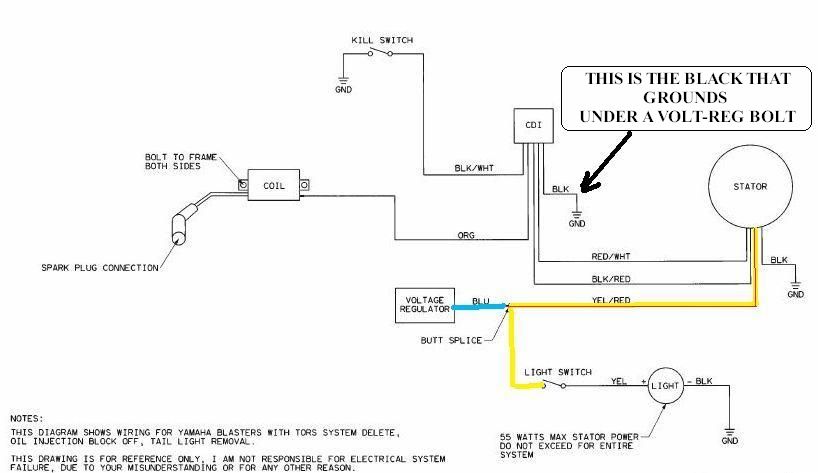
Yamaha Blaster Tors System Wiring Diagram
Circuit connection overview for yamaha blaster tors system wiring diagram, illustrating component connections.

Reference: diagramweb.net
Wiring Diagram For Yamaha Blaster » Wiring Flow Line

This detailed wiring flow line diagram takes it one step further by showing the flow of electricity through each connection point on the TORS system specifically. I’ve found it especially helpful for understanding how the restriction system engages and disengages, depending on the throttle position and safety switches. It breaks down the sequence of wiring paths that enable the system functionality, which is great when you want to troubleshoot or confirm if each wire is functioning properly. If you’ve ever wondered how the system interacts with the throttle components and safety interlocks, this diagram paints a clear picture.
Yamaha Blaster Tors System Wiring Diagram
Circuit connection overview for yamaha blaster tors system wiring diagram, illustrating component connections.

Reference: diagramweb.net
Overall, having access to these Yamaha Blaster wiring diagrams brings clarity and confidence when working on the TORS system. Whether you’re a DIY mechanic or just curious about the electrical workings under the hood, investing time in understanding these schematics can save you hours of frustration and a few trips to the mechanic. Keep these diagrams handy—they’re a real game changer for anyone keen on keeping their Blaster running smoothly and safely!
Yamaha Blaster Tors System Wiring Diagram
Circuit connection overview for yamaha blaster tors system wiring diagram, illustrating component connections.
Reference: diagramweb.net
Circuit Diagram Details
The wiring diagram above provides a visual reference for the electrical system.
Wiring Diagram Summary
Understanding the wiring diagram helps identify electrical circuits, connectors, and components more efficiently during maintenance and troubleshooting.