Wiring Diagram Intimidator Utv Turn Signal Wiring Diagram
This page covers the
wiring diagram, including wire routing,
component wiring, and troubleshooting references.
In the world of off-roading, having a reliable turn signal system on your Intimidator UTV is essential for safety and communication on trails. Understanding the wiring diagram of the turn signal system can help you install, troubleshoot, or upgrade your signals with confidence. This guide provides a clear explanation along with visual references to assist you in mastering the wiring process for your Intimidator UTV turn signal. Whether you are a seasoned mechanic or a UTV enthusiast, this knowledge will enhance your riding experience by ensuring your signals function perfectly.
Understanding the Intimidator UTV Turn Signal Wiring Diagram

The wiring diagram above illustrates the essential components and connections of the Intimidator UTV turn signal system. It highlights the wiring harness, left and right turn signals, flasher relay, and grounding points. Following this diagram carefully helps prevent wiring mistakes that could lead to signal malfunctions. The diagram also provides color-coded wire paths to make it easier for users to identify each connection. Proper grounding and correct relay installation are emphasized to maintain signal integrity and avoiding electrical shorts.
Wiring Diagram Intimidator Utv Turn Signal
Wiring configuration diagram for wiring diagram intimidator utv turn signal, showing wire routing.
Source: diagramweb.net
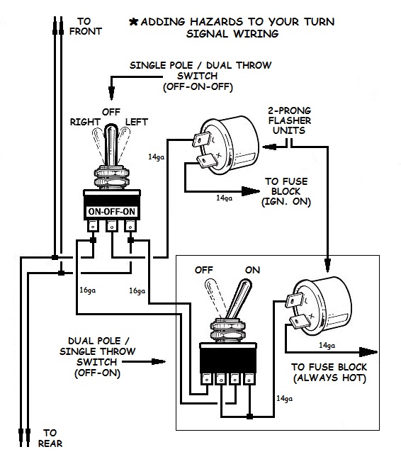
Master the Art of Turn Signal Wiring with These Diagrams

This detailed diagram showcases multiple turn signal wiring configurations, including those suitable for UTVs like the Intimidator. It offers visual clarity for integrating flasher units, switches, and LED or incandescent lamp types. Understanding this broad perspective allows you to customize or troubleshoot a variety of turn signal setups beyond the stock system. Additionally, the diagram demonstrates how to wire the turn signals with hazard lights, enhancing overall vehicle safety. Following such detailed schematics empowers riders to confidently wire up their turn signal systems with precision.
Wiring Diagram Intimidator Utv Turn Signal – Wiring Diagram Pictures
Wiring configuration diagram for wiring diagram intimidator utv turn signal – wiring diagram pictures, showing wire routing.
Reference: schematron.org
Wiring Diagram Intimidator Utv Turn Signal
Wiring configuration diagram for wiring diagram intimidator utv turn signal, highlighting electrical pathways.

Reference: diagramweb.net
Electrical System Overview
Use the diagram as a reference when diagnosing electrical issues or performing repairs.
Conclusion
Understanding the wiring diagram helps identify electrical circuits, connectors, and components more efficiently during maintenance and troubleshooting.